MAX7219 8×8 Dot Matrix (x4) Display Module
MAX7219 8×8 Dot Matrix (x4) Display Module
SKU:IOT/VT/
Share
43 in stock
Couldn't load pickup availability
Description
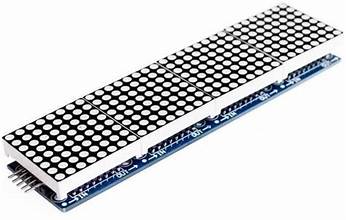
The MAX7219 8×8 Dot Matrix Red Display Module has four 1.3″ 64 LED dot matrix displays with built-in MAX7219 serial LED drivers.
PACKAGE INCLUDES:
- MAX7219 8×8 Dot Matrix (x4) Red Display Module
- 8″ 5-wire F/F cable for hook-up or daisy-chaining multiple displays.
- 5-pin header which can be soldered to the module if daisy-chaining multiple modules together.
KEY FEATURES OF MAX7219 8×8 DOT MATRIX (x4) RED DISPLAY MODULE:
- Four 8×8 LED Matrix Displays with 1.3″ high red displays
- Built-in MAX7219 LED Drivers for each display
- SPI 3-wire serial interface for easy hookup to MCU
- Can daisy-chain multiple modules together for larger displays
MAX7219 LED Driver
The MAX7219 is a popular and flexible 7-segment, bar graph and dot matrix common cathode LED driver that supports many functions for controlling LED displays.
The driver provides flexible individual LED control as well as basic functions such as turning the display ON/OFF and adjusting the LED brightness.
The MAX7219 communicates with an MCU via a 3-wire SPI bus. Once the display is updated by the MCU, the MAX7219 then takes care of all the work of keeping the display refreshed, so it removes that overhead from the MCU which can be off doing other more important things.
SPI Interface
The module communicates via the SPI interface, so it only require 3 data pins to connect to a MCU.
If a larger display is needed, several modules can be daisy-chained together.
Libraries are readily available such as the “LedControl.h” library built-in to the IDE for Arduino that makes communicating with the display very straightforward.
Module Connections
There is an input header on one end and breakout locations on the other end for connecting additional modules.
Input Connector
The header pins on the left end is the main input connector. “Vcc” connects to 5V. Due to the fairly high current draw of the display (up to 1A if the brightness is cranked all the way up), it is recommended to drive it directly from a power supply rather than from the MCU power or else be sure to keep the brightness turned down to < 25% (level 3 of 15) to avoid overheating the MCU on-board voltage regulator or over-taxing the USB power. “GND” connects to ground which needs to be common with the MCU if an external power supply is used.
The other pins are for the SPI interface. “DIN” is the Data In. “CS” is Chip Select (sometimes labeled as LOAD) and “CLK is the Clock pin. These lasts 3 pins are connected to any digital outputs on the microcontroller. Which pins they connect to is defined when an instance of the LedControl is created as shown in the program below.
1 x 5 Header
- VCC – Connect to 5V. Connecting direct to power supply rather than from MCU is recommended.
- GND – Connect to system ground. This ground needs to be in common with the MCU
- DIN – Connect to any digital pin on MCU.
- CS / LOAD – Connect to any digital pin on MCU
- CLK – Connect to any digital pin on MCU.
Output Connector
The break-out pins on the other end of the assembly are used if it is desirable to daisy-chain displays. In this case, the “DOUT” is Data Out and it connects to the next modules “DIN” Data in pin. The other pins are passed straight-thru
1 x 5 Header
- VCC – Connect to 5V on next module if looping power through.
- GND – Connect to GND on next module
- DOUT – Connect to DIN on next module.
- CS / LOAD – Connect to CS / LOAD on next module
- CLK – Connect to CLK on next module
The module ships with the output header loose. This allows you to solder them on the top or bottom of the board or use wires depending on how you want to use the module.