
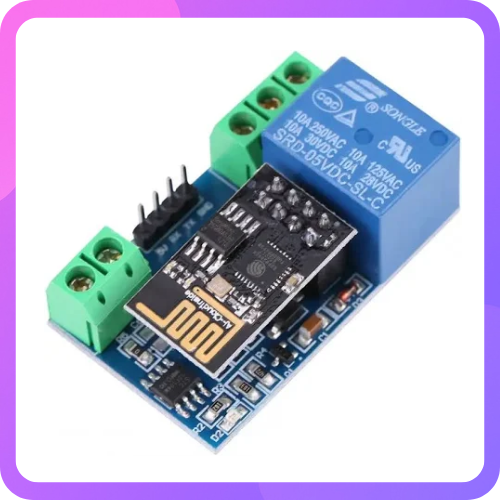
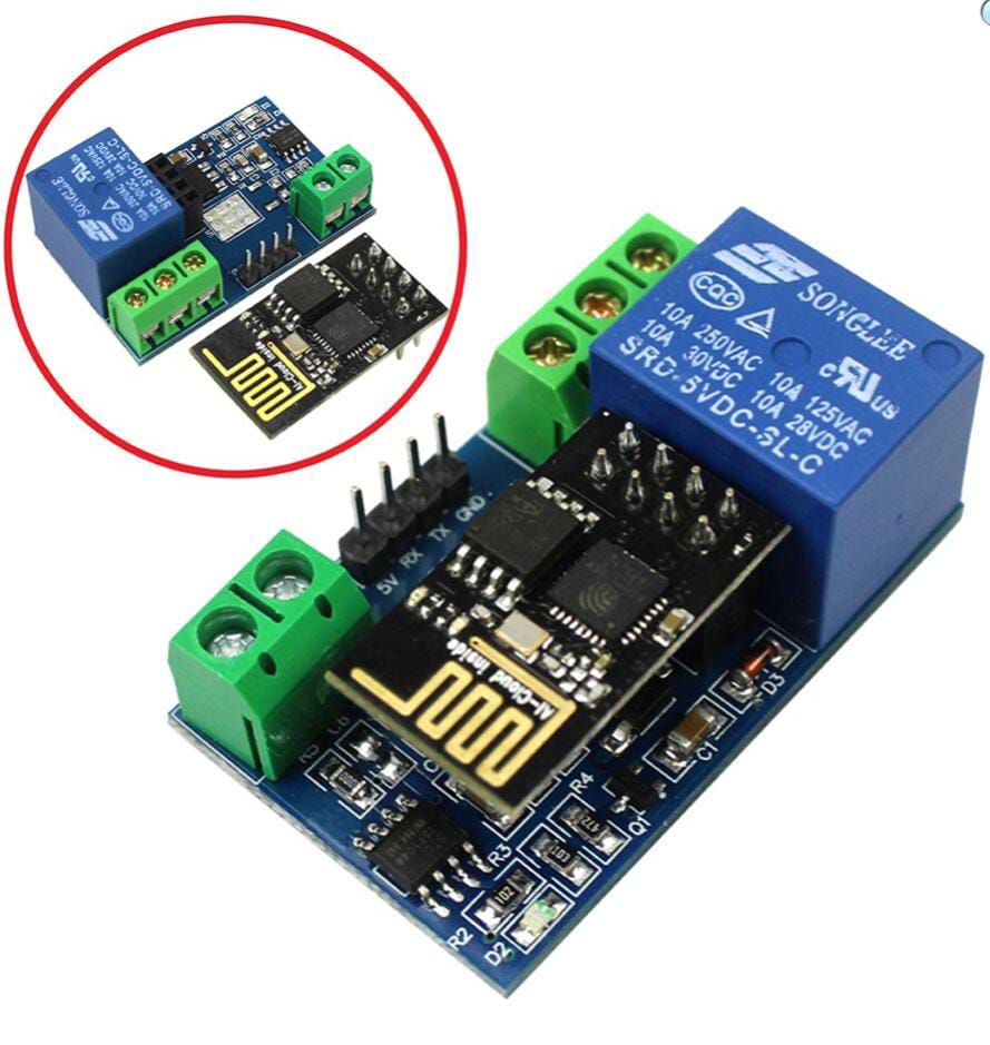
ESP8266 Relay Module — Wi‑Fi Controlled Relay Board
ESP8266 Relay Module — Wi‑Fi Controlled Relay Board
SKU:VT00614
Low stock: 8 left
Couldn't load pickup availability
Description:
The ESP8266 WiFi 5V 1 Channel Relay Module is equipped with an ESP8266 WiFi module and microcontrollers, allowing for wireless control of the relay via a mobile app within a local area network (LAN). This onboard relay supports 5V, 10A / 250V AC and 10A / 30V DC, capable of enduring up to 10 million cycles, featuring overload protection and a fast response time.
How to Use:
The onboard ESP8266 WiFi module offers three operating modes:
- STA (client)
- AP (hotspot)
- STA + AP (client + hotspot)
Select the appropriate mode based on your application. To configure the WiFi module, use serial debugging software on your computer along with a USB to TTL module to send AT commands.
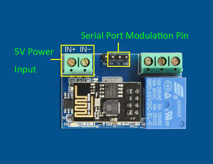
Connect the USB to TTL module’s RX, TX, and GND pins to the corresponding TX, RX, and GND pins on the relay module, and provide a 5V power supply to the IN+ and IN– pins.
Note: This product is available in 2 relay module types:
- JQC3F-5VDC-C
-
SRD-05VDC-SL-C
(It will be shipped randomly.)
General Info:
- Onboard ESP8266 WIFI module, AP mode can be connected at the same time 5 clients
- The module has two ways to work:
(i) Mobile phone directly mounted on the WIFI module
(ii) Mobile phone and WIFI module also carried on the router -
Transmission distance:
- Open environment: The mobile phone mounted on the WIFI module when the maximum transmission distance is 400m
- When the WiFi module and mobile phone are carried on the router: transmission distance depends on the router’s signal strength
Board function description:
- IN +, IN-: 5V power input
- TX, RX, GND: Serial debug pin
The onboard ESP8266 WiFi module offers three operational modes:
-
STA (client)
-
AP (hotspot)
-
STA + AP (client + hotspot)
Depending on the intended use of the module, you should select the appropriate WiFi operating mode. Before using the module, configure it by sending serial commands via serial debugging software and a USB to TTL module.
It’s important to ensure that the module remains powered on after configuration, as some WiFi parameters may not be saved if power is lost. Once a network connection is established between your mobile phone and the WiFi module, you can use a mobile app to control the relay.
Control Commands:
When a cell phone equipped with WiFi module sends commands in the following order:
(The default baud rate is 115200)
- AT+CWMODE=2, namely AP mode is selected.
- AT+RST, reset.
- AT+CIPMUX=1, open multiple connections.
- AT+CIPSERVER=1,8080, configure the TCP server, set the port.
- AT+CIOBAUD=9600, set the baud rate to 9600 (working in relays to control the baud rate 9600).
- AT+CIFSR, to view the AP mode IP address, such as the APIP, “192.168.4.1”.
- Cell phone WiFi signal connection name starts with AI-THINKER or ESP8266.
- In the “TCP connection” address and port, enter the APP, such as 192.168.4.1 and 8080.
- Click on the grey box in the app to control the relay.
Features:
- Onboard Module: ESP8266 WiFi module; in AP mode it can connect with 5 Clients at the same time
- Operating Way:
- Cellphone connected directly to the WiFi module
- Cellphone and WiFi module connected to the same router, and use the APP to control relay
- Diode effusion protection
- Short response time
Specification:
| Model Type: | Relay Module |
|---|---|
| No. of Channels: | 1 |
| Transmission Distance | 400m (max) |
| Trigger Voltage (VDC) | 5 |
| Switching Voltage (VAC) | 250@10A |
| Switching Voltage (VDC) | 30@10A |
| Baud Rate (bps) | 9600 |
| Length (mm): | 45 |
| Width (mm): | 28 |
| Height (mm): | 20 |
Package Includes:
- 1 x ESP8266 WiFi 5V 1 Channel Relay Module
